Aluminum Dice
This is a good starter project for getting used to working with a vertical mill.
We'll cover how to create a perfect cube, chamfering, and position repeatability.
When starting a lot of projects on the a vertical milling machine, it will be necessary to true up the sides of the workpiece before you can begin milling in earnest. This is due to inconsistencies in the surfaces and angles of rough-cut materials, even extruded bar stock can have enough variation that you need to clean it up if you're doing precise work.
Rough Cut the Stock
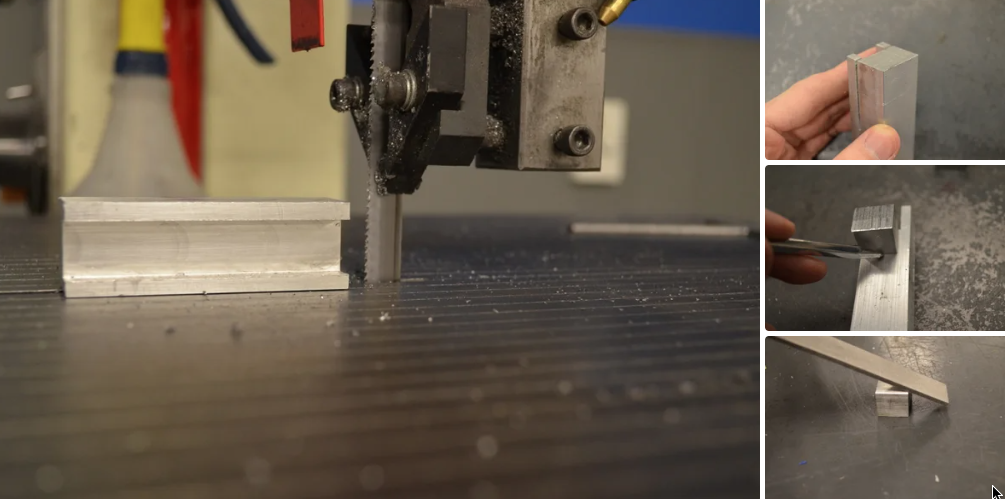
Whenever possible, you should cut your stock down to fairly close to what the finished product will be before you take it to the mill. This will cut down both on the time your project will take (a bandsaw is definitely faster than a mill for cutting bar stock to length) as well as reduce wear-and-tear on both the mill and tooling. Your goal should be to be able to use the bandsaw to get the stock to a size where you will be able to make just one rough cut with the mill to to square each face of the stock, and then one finishing cut (around .001 inch) to bring it to the proper size.
Cut your stock slightly larger (say .24") than the desired dimensions of your dice.
After making rough cuts on the bandsaw, none of the sides will be flat, nor at a 90% angle to any adjacent faces.
Before we can do the more precise milling aspects of this project, we need to square up the rough cut pieces so that each face of the workpiece is perpendicular to the adjacent faces.
Cut the First Face
Since there are no true dimensions which can be trusted to be used as a reference for creating the other faces, we can be somewhat cavalier about the positioning of the piece as we prepare to cut the first face of our workpiece. Of course, we don't want the piece to be at completely the wrong angle, but this is the one time where eyeballing it will be good enough.
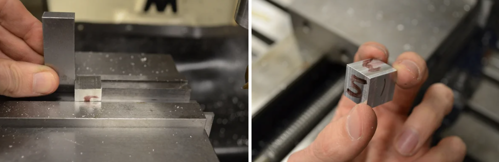
Select a parallel that will permit a large portion of your workpiece to be held by the jaws of the vise, but will also permit enough of the workpiece to protrude above the vise that you can machine material off of the top.
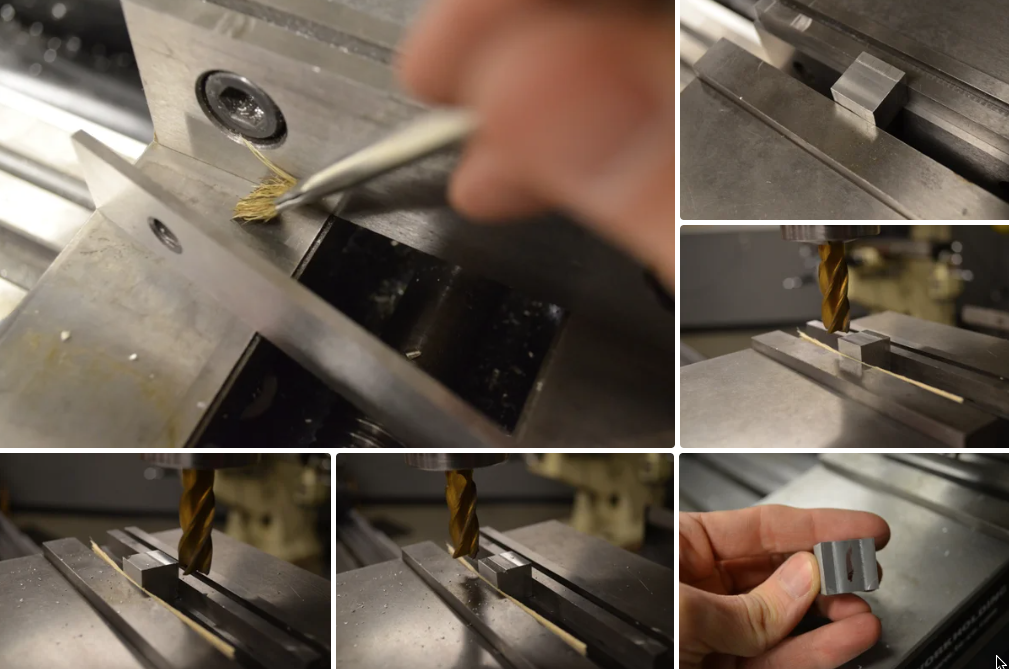
Use a brush and clean out any chips from between the jaws of the vise. Place one parallel in the mill's vise, against the stationary jaw of the vise. Rest your workpiece on top of the parallel and close the jaws most of the way. When you get close, insert the small scrap of wood between the workpiece and the movable jaw of the vise, then close the vise firmly. The wood will deform against the uneven edge of the workpiece and help prevent it from wobbling between the vise jaws.
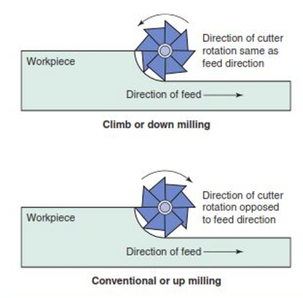
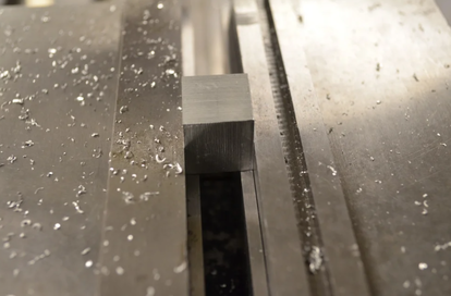
Turn on the mill and lift the table until the top of the workpiece touches the bottom of the end mill. Raise the table another couple thousandths of an inch and then mill away all the material on that plane. Using climb cutting around the outside edges to help prevent burrs. Once you have faced the piece, double-check to make sure that you have milled away all of the band saw marks. If not, raise the table another couple of thousandths and repeat the process until you have a flat surface.
Turn off the mill and remove the workpiece from the vise. Use a metal file to remove any burrs, and mark the newly machined face with the number '1'. We will be trying to machine all of the other faces so they are in proper orientation with relation to this face, which will be our most 'true' (all others being subject to some small amount of error due to imperfections and misalignment in the mill.
Select a parallel that will permit a large portion of your workpiece to be held by the jaws of the vise, but will also permit enough of the workpiece to protrude above the vise that you can machine material off of the top.
Use a brush and clean out any chips from between the jaws of the vise. Place one parallel in the mill's vise, against the stationary jaw of the vise. Rest your workpiece on top of the parallel and close the jaws most of the way. When you get close, insert the small scrap of wood between the workpiece and the movable jaw of the vise, then close the vise firmly. The wood will deform against the uneven edge of the workpiece and help prevent it from wobbling between the vise jaws.
Turn on the mill and lift the table until the top of the workpiece touches the bottom of the end mill. Raise the table another couple thousandths of an inch and then mill away all the material on that plane. Using climb cutting around the outside edges to help prevent burrs. Once you have faced the piece, double-check to make sure that you have milled away all of the band saw marks. If not, raise the table another couple of thousandths and repeat the process until you have a flat surface.
Turn off the mill and remove the workpiece from the vise. Use a metal file to remove any burrs, and mark the newly machined face with the number '1'. We will be trying to machine all of the other faces so they are in proper orientation with relation to this face, which will be our most 'true' (all others being subject to some small amount of error due to imperfections and misalignment in the mill.
Cut the Second Face
Place the workpiece back into the vise resting atop the parallel with side '1' facing the stationary jaw of the vise. Use the wood scrap again between the movable jaw and the workpiece. It is important that side '1' is flush with the jaw, so make sure that it doesn't cam at an angle as you close the vise.
Repeat the facing process from the previous step.
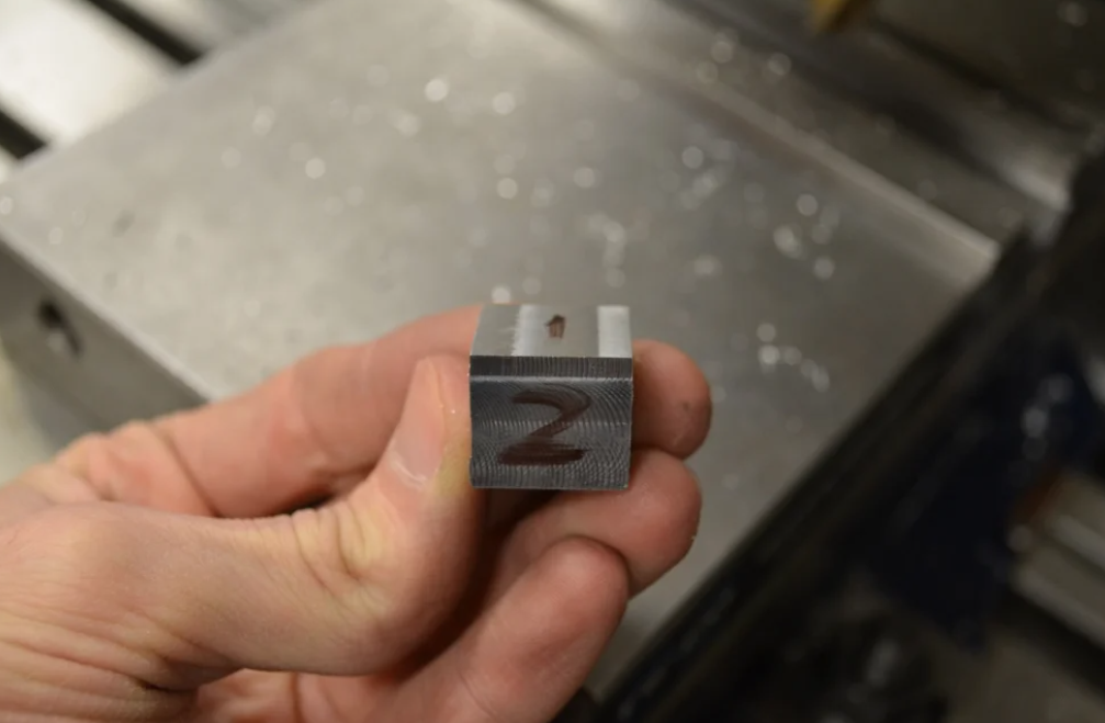
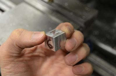
Remove the workpiece from the vise, remove any burs. I've marked mine with a '2'.
Repeat the facing process from the previous step.
Remove the workpiece from the vise, remove any burs. I've marked mine with a '2'.
Cut the Third Face
Clean any chips off of the parallel and place the workpiece back in the vise with side '1' facing the stationary jaw of the vise and side '2' facing down (touching the parallel). Close the vise using the wood scrap between the movable jaw and the workpiece.
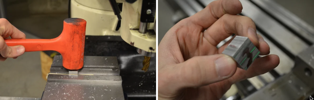
Tap the top of the workpiece with a mallet to seat it firmly against the parallel. You will want to do this any time a machined side of the workpiece is facing down. Remember that the front edge of the die is unsupported underneath, so only tap on the back half. The die should be seated flush with both the face of the stationary jaw and the top of the parallel.
Machine the top of the workpiece flat.
Remove the workpiece from the vise and remove any burs. I've marked this as side '3'.
Cut the Fourth Face
Clean any chips from between the jaws of the vise. Place the second parallel into the vise against the movable jaw. Place the workpiece into the vise with side 1 facing down (touching the parallels), side '2' against the stationary jaw of the vise, and side '3' against the movable jaw.
Close the jaws of the vise and tap the top of the workpiece with a mallet to seat it firmly against both parallels.
Machine off the surface of the workpiece.
Remove the workpiece and remove any burs. I've marked this as side '4'.
Close the jaws of the vise and tap the top of the workpiece with a mallet to seat it firmly against both parallels.
Machine off the surface of the workpiece.
Remove the workpiece and remove any burs. I've marked this as side '4'.
Cut the Fifth Face
Brush any chips out from between the jaws of the vise.
Place the workpiece with side '1' facing the stationary jaw of the vise and side '2' facing to the left.
Use a machinists square to align the workpiece so that side 2 is perpendicular to the top of the stationary jaw of the vise. In the photo the square is pointing up, but you will get more surface contact if the square points down into the vise (assuming it is short enough to not bottom-out in the vise).
Clamp the vise while holding the workpiece at 90 degrees with the square.
Machine the face flat.
Remove the workpiece from the vise and remove any burs. I've marked mine with a '5'.
Cut the Sixth Face
Remove any chips from between the jaws of the vise.
Clamp the workpiece into the vise with side '1' against the stationary face of the vise and side '5' facing down against the parallels. Use a mallet to seat the workpiece.
Machine the face flat.
You will sometimes want to use the 'Z' depth of your final cut as a starting point for whatever the next step in your machining project will be. If so, set your 'Z' axis indicator dial to zero to preserve the position.
Remove the die from the vise and remove any burs.
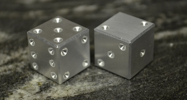
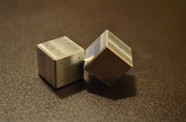
You now have a precision milled piece with 90 degree angles between the faces.
Clamp the workpiece into the vise with side '1' against the stationary face of the vise and side '5' facing down against the parallels. Use a mallet to seat the workpiece.
Machine the face flat.
You will sometimes want to use the 'Z' depth of your final cut as a starting point for whatever the next step in your machining project will be. If so, set your 'Z' axis indicator dial to zero to preserve the position.
Remove the die from the vise and remove any burs.
You now have a precision milled piece with 90 degree angles between the faces.
Calculate Depth of Final Cuts
Right now we have a workpiece that should have faces at 90 degrees from each other, but the size in the X, Y, and Z axes will each be different. We need to bring all of those dimensions to the desired dimension of our finished die.
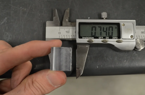
In my case I was aiming for a 0.65 inch cube. Using digital calipers I measured the distance from the bottom face to the top face. This gives us the distance from the top of the parallels to the bottom of the end mill, assuming we haven't moved the Z axis of the mill since making a skim pass on the top face.
Subtracting our desired dimension from the current dimension of the die gives us the amount of material that needs to be removed.
.740 - 0.650 = 0.09 inches.
Cut the Final Dimensions
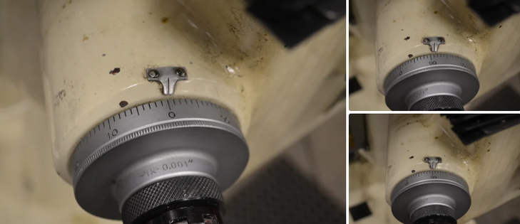
Set the z axis dial to zero, then crank the height to the desired cut depth.
If machining to tight tolerances, we would remove that material in two passes, the first pass at .089 inches, then a finishing pass of an additional .001 inches. If you don't really care about being exact, feel free to just make one pass at .090.
You should always try to keep the most precise sides of the die in contact with the fixed jaw and the parallels of the vise as you machine down the rest of the die.
Machine each of the three dimensions of the cube to the proper dimension by milling one side, then rotating the die in the vise without moving the Z axis.
All three sides of our workpiece should now be the same dimension, giving us a perfect cube.
Chamfer the Edges
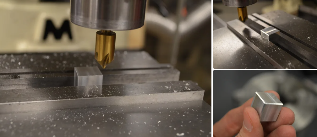
Remove the end mill from the mill and install a countersink bit.
Position the cutter so that the mill is above the movable jaw of the chuck. The closer you can get to the vise in the 'Z' axis the better, since you will get a larger diameter of the cutting surface in contact with your workpiece. If just the tip of the countersink touches your workpiece, you will get a lousy finish. Lock your 'Z' axis.
Turn on the mill and move the piece in the Y axis until the cutter bites into the workpiece. Move the workpiece in the 'X' axis, removing the sharp edge between two of the machined faces of the die. If you want to create a bigger chamfer, push further into the piece using the 'Y' axis and make another pass. Once you are satisfied with the size of the chamfer, lock your 'Y' axis.
Park the cutting tool to one side of the workpiece, Turn off the mill and unclamp the vise. Rotate the workpiece so that an unchamfered edge is visible above the movable jaw of the vise. Turn the mill back on and make a pass across the workpiece in the 'X' axis. This should put the exact same chamfer on the new edge that you put on the first edge.
Repeat this process for each edge of the cube.
I found that since the countersink I was using had several flutes, the aluminum chips sometimes got pulled back around to the workpiece instead of being thrown clear, and would gall slightly on the first pass of a chamfer. Simply making a second pass without moving the 'Y' axis removed any galling from the first pass and cleaned up the edge nicely. Using a countersink with fewer flutes would have helped prevent the galling, but I did not have one on hand.
Calculate the Dot Positions
We will need to divide the face of the die into a 3 by 3 grid, leaving a small border around the outside.
In this example I will leave a 5% border.
divide the total length of a side by 10 and subtract that from the length of one side. That leaves us conveniently with 90% to divide by 3, giving 30% for the width and height of each square of the grid.
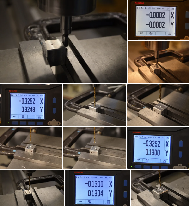
We really only need to calculate three x,y coordinate pairs. Those three positions can be used to drill all of the dots by repositioning the die below the drill bit.
Top left:
x = border + half of a grid square
= 5% + 15%
= 20%
= 0.13
y = same as x
= 0.13
Top Center:
x = 50%
= 0.325
y = same as top left y
= 0.13
Middle Center:
x = 50%
= 0.325
y = 50%
= 0.325
In this example I will leave a 5% border.
divide the total length of a side by 10 and subtract that from the length of one side. That leaves us conveniently with 90% to divide by 3, giving 30% for the width and height of each square of the grid.
We really only need to calculate three x,y coordinate pairs. Those three positions can be used to drill all of the dots by repositioning the die below the drill bit.
Top left:
x = border + half of a grid square
= 5% + 15%
= 20%
= 0.13
y = same as x
= 0.13
Top Center:
x = 50%
= 0.325
y = same as top left y
= 0.13
Middle Center:
x = 50%
= 0.325
y = 50%
= 0.325
Rough Mark the Dots
Just to make sure the holes get drilled in the right spots, it is a good idea to mark the faces with a marker before drilling.
One rule you must follow is that opposing sides of a die must add up to 7. That means that 1 is opposite 6, 2 is opposite 5, and 3 is opposite 4.
One rule you must follow is that opposing sides of a die must add up to 7. That means that 1 is opposite 6, 2 is opposite 5, and 3 is opposite 4.
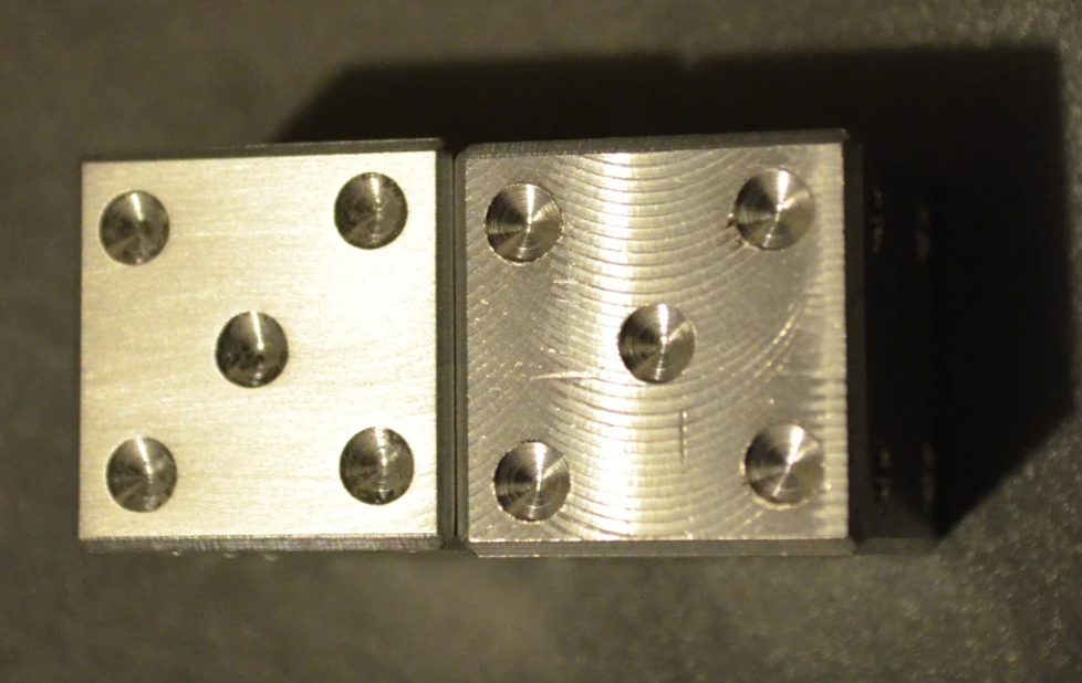
Drill the Dots
Attach a clamp to the fixed jaw of the vise to use as a repeatable stop in the x axis.
Clamp the die in the vise so that it is butted up against the clamp you just attached to the vise. Be sure that side '1' is facing up.
Use an edge finder to zero the X and Y axes over the top left corner of the die.
Swap a drill bit into the mill. The bit needs to be smaller than the size of the grid squares in order for there to be space between holes drilled in adjacent squares. I ended up drilling with a 0.1 inch bit, which was just about right for the aesthetic I wanted. I did use a long drill bit, and the bit did wander a noticeably due to deflecting. The shorter the bit, the more accurate your holes will be.
Center the drill over the die using the X and Y coordinates from the previous step.
Temporarily lock the quill at the bottom of its travel. Use the knee adjustment to bring the workpiece up to the drill.
Turn on the drill and begin to drill by slowly raising the workpiece. When you are satisfied with the size of your hole, stop raising the the workpiece, unlock the quill, and raise the drill bit away from the workpiece. You can now quickly repeat the depth of that hole by dropping the quill to its bottom position.
Drill out all remaining center holes (we just did side 1, do 3 and 5).
Move to the top middle X/Y position and drill out the two side holes on side 6.
Move to the top left X/Y position and drill out all of the corner holes (sides 2, 3, 4, 5, and 6).
Sand the Dice
Place a 400 grit sandpaper on a flat surface and drag each face of the dice across it firmly until all of the curved lines from the milling process have been removed.
Smoothing down the points of the die just a little bit as well is probably a good idea to help prevent the dice scratching each other when they touch. Some marring is going to be inevitable over time, but this will slow down that process somewhat.
Smoothing down the points of the die just a little bit as well is probably a good idea to help prevent the dice scratching each other when they touch. Some marring is going to be inevitable over time, but this will slow down that process somewhat.