Technical Drawings & Material Lists
It's time for you to step up your game!
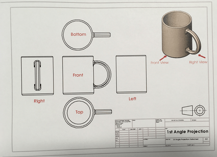
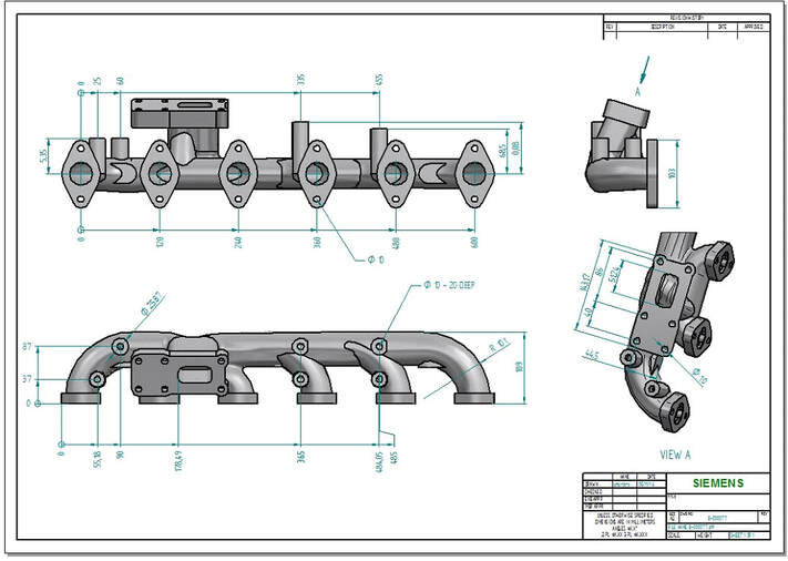
As an Advanced Student or when proposing a project, I expect you to provide me with plans in the form of Technical Drawings for you individualized driven projects, that provide measurements and multiple views of your project.
In addition, I would like to see professional material lists.
For example...
2' 1/2" Square Stock
10' 2" Square Tube
2' x 1' 1/4" Plate Steel
2' x 3 1/2' Expanded Steel
Orthographic Drawing
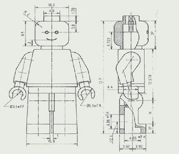
Orthographic drawing is a way of drawing a three dimensional object. Normally the object is drawn as three separate, related views - Front View, Side View and Plan View.
The example below shows a simple shaped block, with a hole drilled all the way through.
The front view, is a drawing of the block, as if you are looking directly at the front of the object.
The side view, is a drawing of the block, when it has been rotated so that one of its sides is now directly in view.
The plan view, is a ‘birds eye’ view, from above.
Dotted lines represent ‘hidden detail’. In this case they represent the hole, through the block/object.
The front, side and plan views are arranged in the positions shown below. They must be drawn accurately.
Draw the front view first, followed by the side view. The plan view is drawn directly above the front view. Note, a 45 degree line allows the projection of the side view to the plan view.
Dimensions (measurements) are added to the completed views. Usually six dimensions are added. This enables anyone looking at the orthographic drawing, to work out the overall size of the object. More dimensions can be added if necessary. Dimensions are drawn on each of the views.
The Language of Lines
- OBJECTLINE
- HIDDEN LINE
- SECTION LINE
- CENTER LINE
- DIMENSION LINE
- EXTENSION LINE
- LEADER LINE
- CUTTING PLANE LINE
- BREAK LINES
- PHANTOM LINES
- BORDER LINE
You have heard the saying, “A picture is worth a thousand words”. This statement is particularly true in regards to technical drawings.
It would be almost impossible for an engineer, designer, or architect to describe in words the shape, size, and relationship of a complex object. Therefore, drawings have become the universal language used by engineers, designers, technicians, as well as craftsmen, to communicate the Information necessary to build, assemble and service the products of industry.
It is Important to remember, as you study Print Reading, that you are learning to communicate with the graphic language used by Industry: Lines are part of that language.
Since technical drawings are made of lines, it is logical that the first step in learning to “read” a drawing is to learn the meaning of each kind of line. Generally, there are 11 basic types of lines. Each kind of line has a definite form and “weight”. Weight refers to line thickness or width. When combined in a drawing, lines provide part of the Information needed to understand the print.
Being able to interpret a blueprint and accurately build objects is a needed skill to become successful in all trade crafts. It is a skill, like many others you will learn, and it will take time and practice to fully understand and become proficient.
Object Line
A visible line, or object line is a thick continuous line, used to outline the visible edges or contours of an object.
Hidden Line
A hidden line, also known as a hidden object line is a medium weight line, made of short dashes about 1/8” long with 1/16”gaps, to show edges, surfaces and corners which cannot be seen. Sometimes they are used to make a drawing easier to understand. Often they are omitted in an isometric view.
Section Line
Section lines are used to show the cut surfaces of an object in section views. They are fine, dark lines. Various types of section lines may indicate the type of material cut by the cutting plane line.
Center Line
Center lines are used to indicate the centers of holes, arcs, and symmetrical objects. They are very thin (size), long-short-long kinds of lines.
Dimension Line
Dimension lines are thin and are used to show the actual size of an object. There are arrowheads at both end that terminate at the extension lines.
Extension Line
Extension lines are also thin lines, showing the limits of dimensions. Dimension line arrowheads touch extension lines.
Leader Line
Leaders are more thin lines used to point to an area of a drawing requiring a note for explanation. They are preferably drawn at a 45° angles.
Cutting Plane Line
A cutting plane line (very heavy) helps to show the internal shape at a part or assembly by slicing through the object.
Break Line
There are three kinds of break lines used in drawings. They are used to remove, or ‘break out” part of a drawing for clarity, and also to shorten objects which have the same shape throughout their length and may be too long to place on the drawing. Short and long break lines are used for flat surfaces. Cylindrical are used on rods, dowels, etc.
Phantom Line
Phantom lines are long-short-short-long lines most often used to show the travel or movement of an object or a part in alternate positions. It can also be used to show adjacent objects or features.
Border Line
Borderlines are very thick, continuous lines used to show the boundary of the drawing or to separate different objects drawn on one sheet. They are also used to separate the title block form the rest of the drawing.
Working Drawing
A working drawing is the final ‘constructed’ drawing, produced as part of the design process. It usually consists of a front, side and plan view of the solution. Sometimes there are two views but this depends on the complexity of the solution. Dimensions are added so that any person using the working drawing can manufacture the design. Usually there are at least six dimensions but you can add as many as you feel are required in order for the manufacturer to make your solution.
The working drawing should be precise and drawn to a scale. If the drawing is half the size of the solution then the scale is 1:2. If the drawing is a 3rd the size of the solution then the scale is 1:3.
Use a 2H pencil or a fine black pen for the final outline. This will allow the drawing to stand out. The dimensions are usually quite faint apart from the arrow heads and the measurement.
A ‘Parts List’ is a very important feature of the working drawing as all the parts are listed, with measurements. The materials used are also mentioned as well as the finish applied to the individual pieces.